

ESPrtk diagram.
Let’s have a look again at ESPrtk diagram circuit.
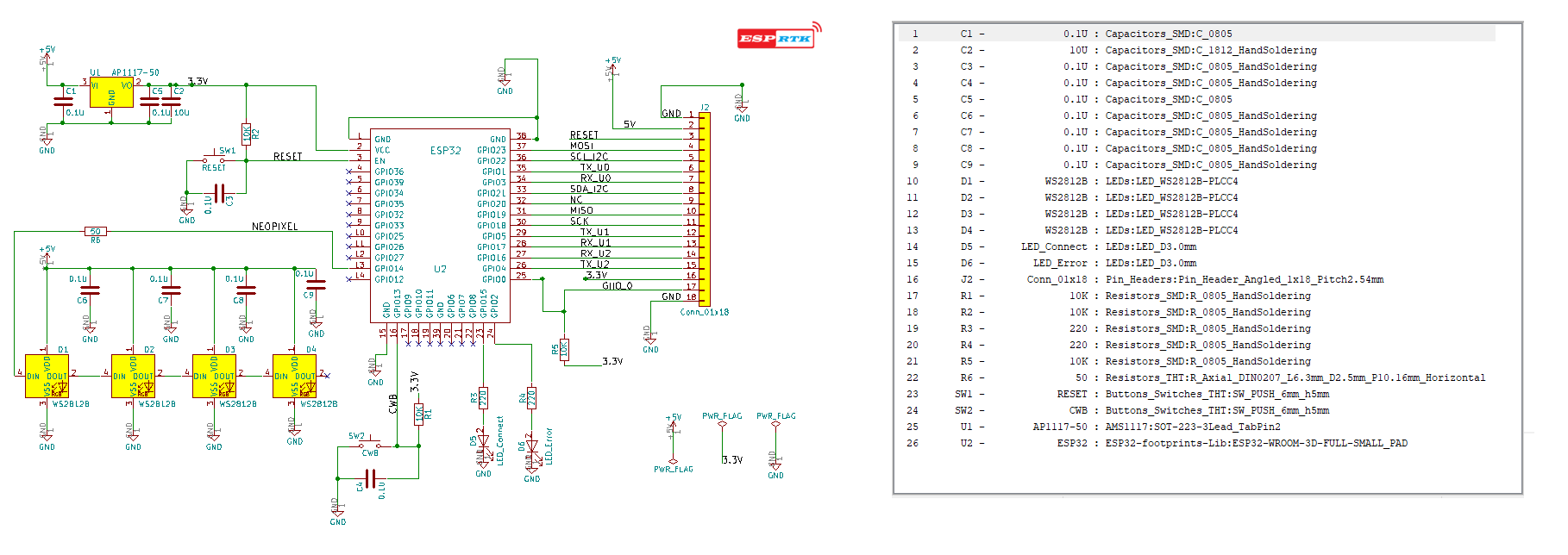
 esprtk circuit diagram v1 (Full size)
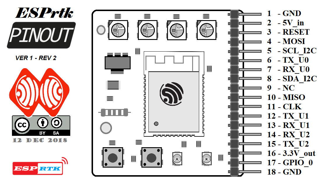 ESPrtk board V1 pinout mapping (Full size)
Minimum requirements for ESPrtk to operate:
– Main ingredient :
+ 1 module ESP32 .
+ 2 Led single .
+ 1 power supply 3.3V .
+ 4 Neopixel WS28128B.
+ 2 buttons (Reset and CWB).
+ Some resistor and capacitor …
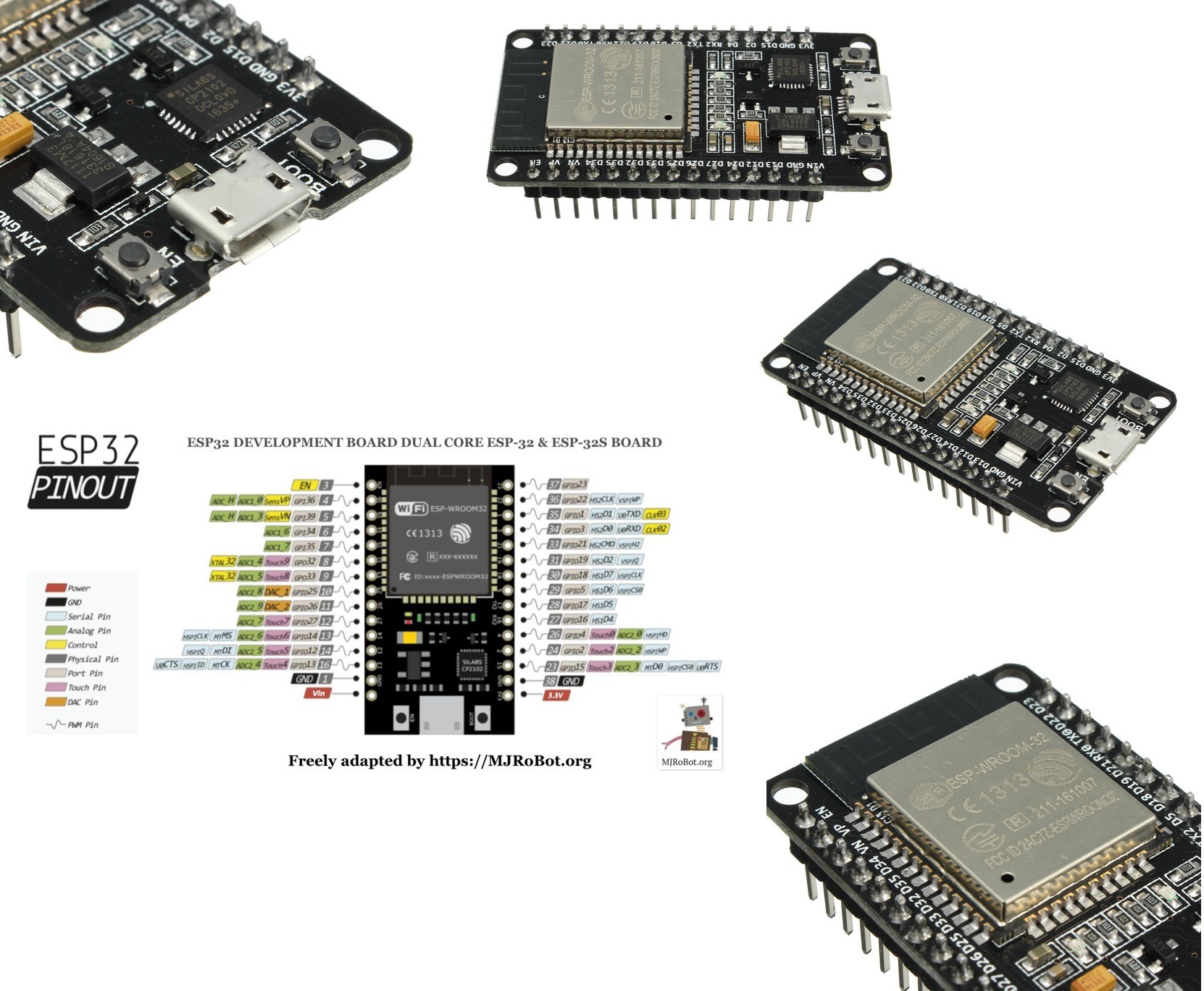
– The recommended ESP32 module should be the development board supporting the output pins as much as possible.
For ease of use, the output pins should be welded. USB cable support, Auto program load, compact size will be the criteria when choosing.
The modified version of silicon on the ESP32 core should be the latest (currently Rev 1). To check ESP32 status you can view this post: WebConfigure :About.
Where to buy these electrical components?
You can almost buy it in every electronic store in the world. They are definitely on some e-commerce websites like Ebay, Amazon or Alibaba-Aliexpress. The total amount to create an ESPrtk DIY development board like this is about $20 or less.
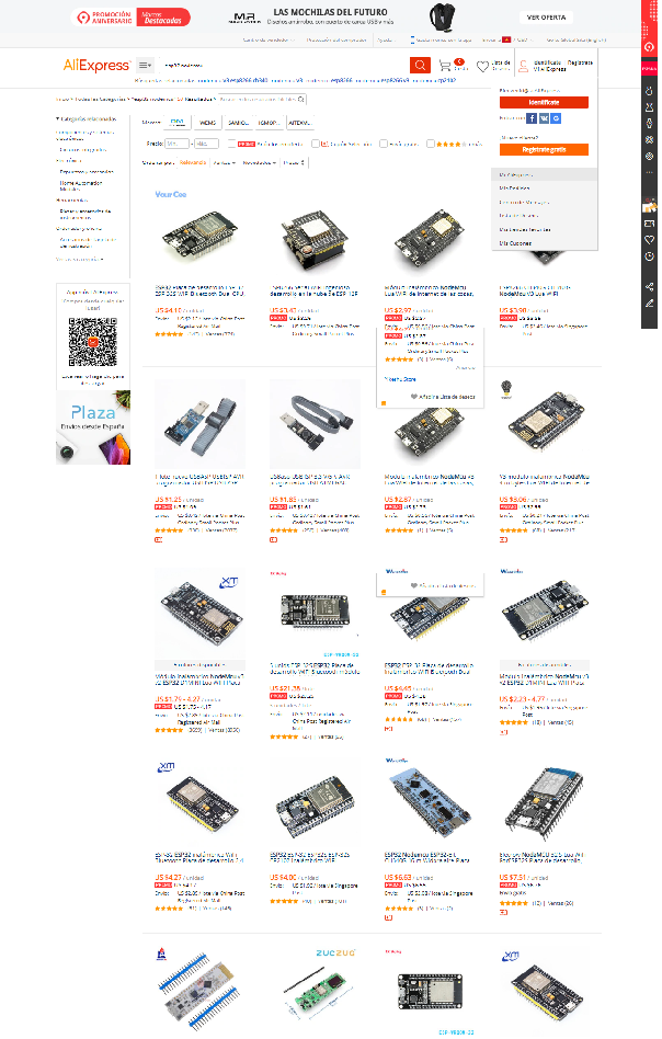
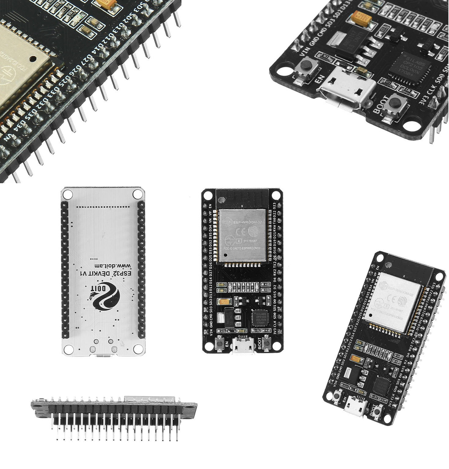
There are some development boards that are suitable for use.
ESP32 DEVKITC board : (Full size)
ESP32 GEEKCREIT board :(Full size)
ESP32 GEEKNET32 board: (Full size)
ESP32 NODEMCU32S : (Full size)
and many other boards ….
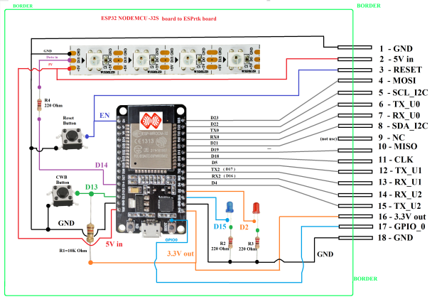
Component wiring for NODEMCU32S.
Component :
- ESP32 NODEMCU32S board : 1.
- Neopixel Strip 4 LED WS28128B: 1 .
- Push button :2
- Resistor 220 Ohm :3.
- Resistor 10K Ohm : 1.
- Single LED (Blue /Red) : 2.
Wiring as bellow image:
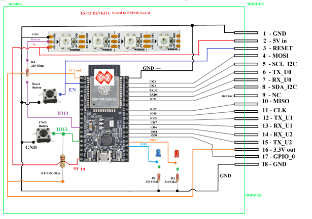
Component wiring for DEVKITC
Component :
- ESP32 DEVKITC board : 1.
- Neopixel Strip 4 LED WS28128B: 1 .
- Push button :2
- Resistor 220 Ohm :3.
- Resistor 10K Ohm : 1.
- Single LED (Blue /Red) : 2.
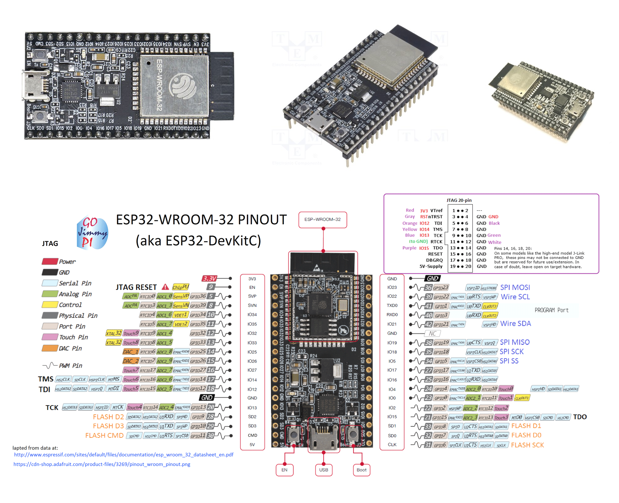
Wiring as bellow image:
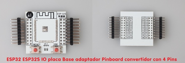
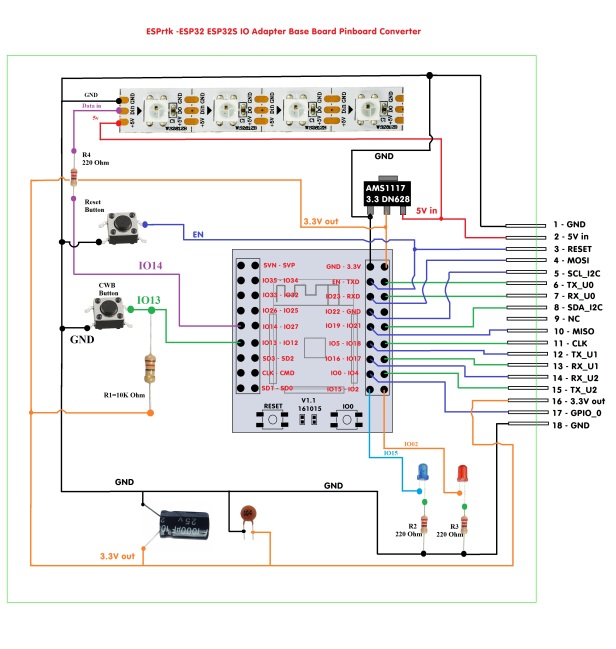
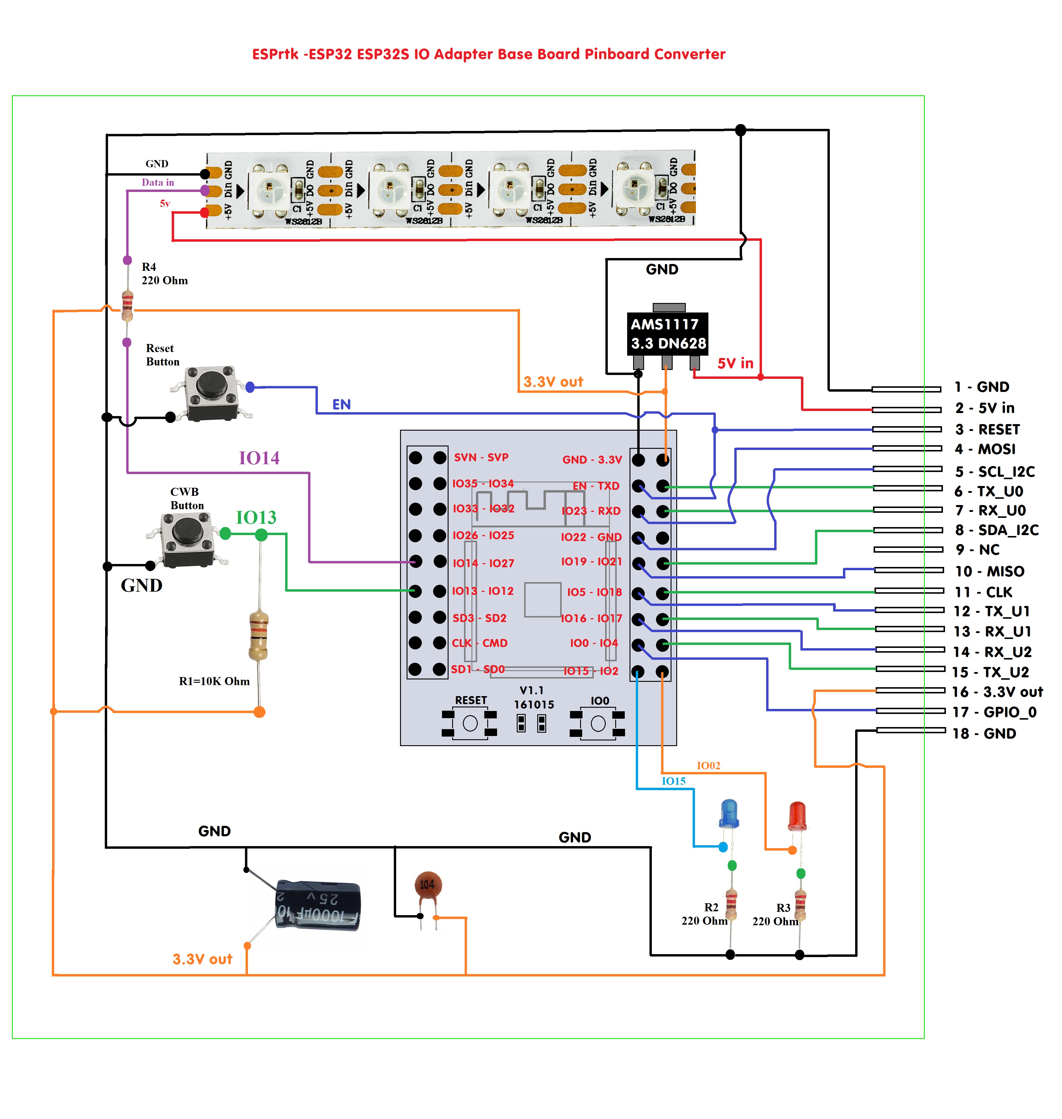
Component wiring for ESP32S IO Adapter Base Board Pinboard Converter With 4 Row Pins
Component :
- ESP32 IO Adapter Base board : 1.
- Neopixel Strip 4 LED WS28128B: 1 .
- Push button :2.
- ASM1117 3.3V: 1 .
- Resistor 220 Ohm :3.
- Resistor 10K Ohm : 1.
- Single LED (Blue /Red) : 2.
Wiring as bellow image:
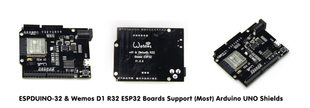
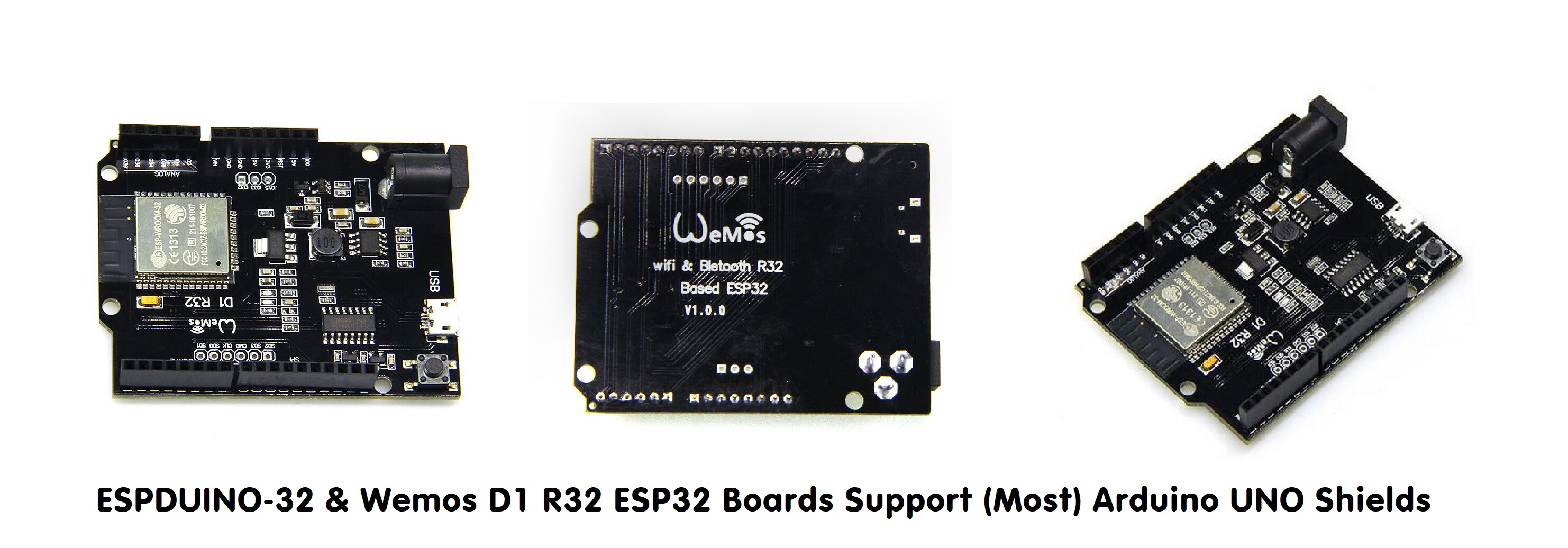
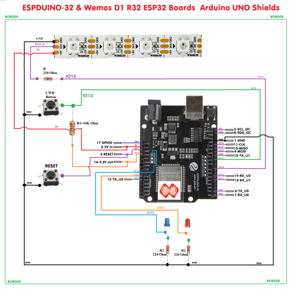
Component wiring for ESPDUINO-32 & Wemos D1 R32 ESP32 Boards – Arduino UNO Shields
Component :
- ESPDUINO-32 & Wemos D1 R32 ESP32 Boards -Arduino UNO Shields: 1.
- Neopixel Strip 4 LED WS28128B: 1 .
- Push button :2.
- Resistor 220 Ohm :3.
- Resistor 10K Ohm : 1.
- Single LED (Blue /Red) : 2.
Wiring as bellow image:
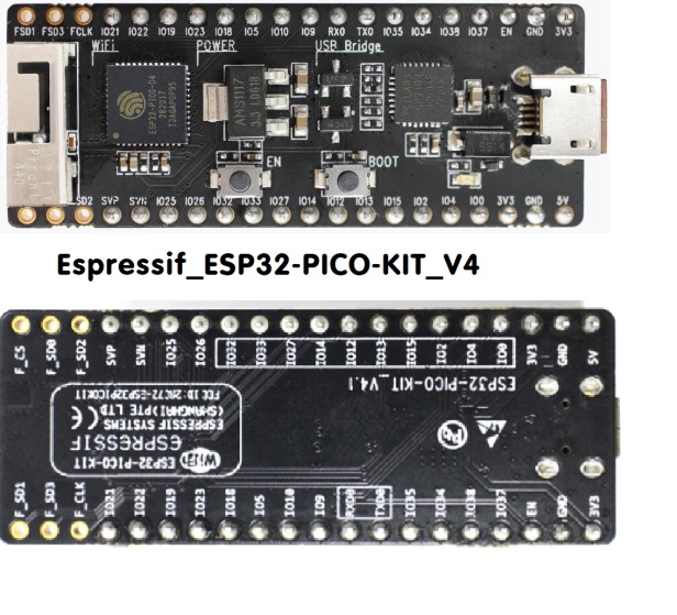
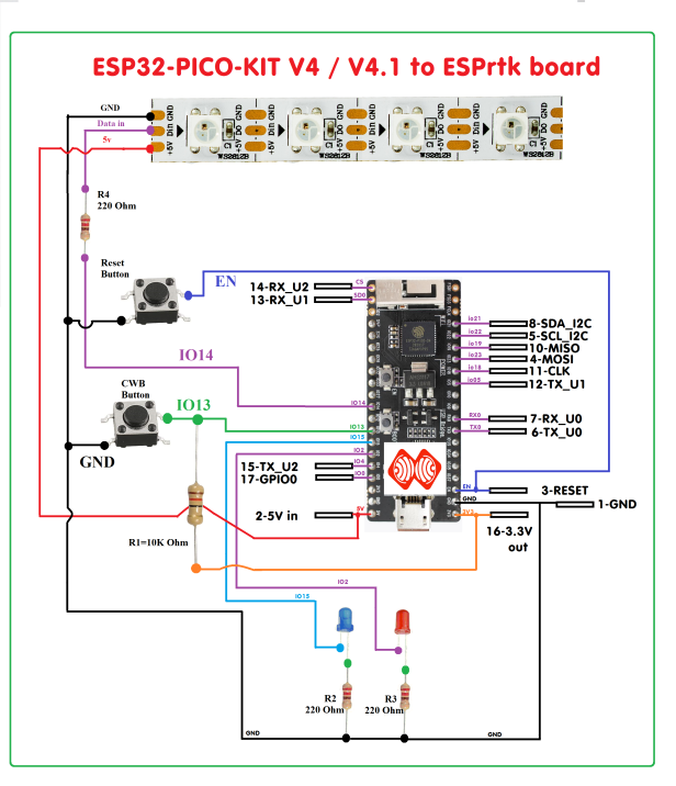
Component wiring for Espressif_ESP32-PICO-KIT V4
Component :
- ESP32 PICO V4 board : 1.
- Neopixel Strip 4 LED WS28128B: 1 .
- Push button :2.
- Resistor 220 Ohm :3.
- Resistor 10K Ohm : 1.
- Single LED (Blue /Red) : 2.
Wiring as bellow image:
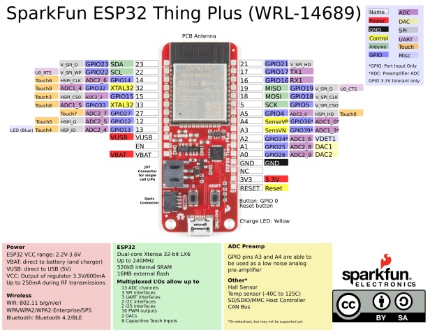
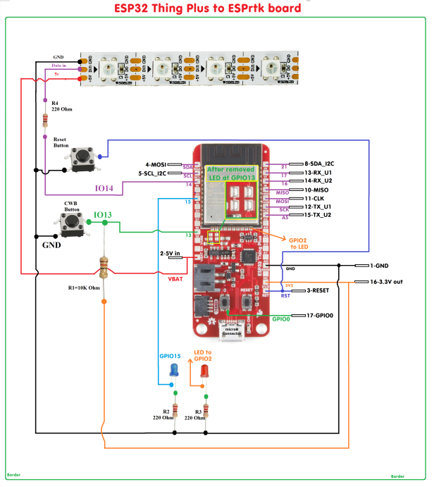
Component wiring for ESP32 Thing Plus
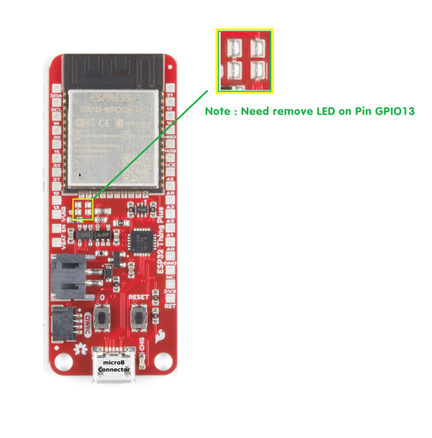
Note: This module is missing the output pin GPIO0, GPIO02, TX_UART0, RX_UART0 on the main board. You need to connect directly to ESP32 module if you want to use those pins.We need to remove LED (that connect to pin GPIO13 on ESP32) because GPIO13 will use for CBW button .Component :
- ESP32 Thing Plus : 1.
- Neopixel Strip 4 LED WS28128B: 1 .
- Push button :2.
- Resistor 220 Ohm :3.
- Resistor 10K Ohm : 1.
- Single LED (Blue /Red) : 2.
Wiring as bellow image:
Note: This module is missing the output pin GPIO0, GPIO02, TX_UART0, RX_UART0 on the main board. You need to connect directly to ESP32 module if you want to use those pins.
We need to remove LED (that connect to pin GPIO13 on ESP32) because GPIO13 will use for CBW button .
Component wiring for another boards.
The ESP32 development boards are quite similar because they use the same single chip as the ESP32 WROOM 32S. They differ only in the arrangement of the output locations, just look at the pinout mapping table on that board and then match the original ESPrtk schematic provided at the top of the page to be able to connect success.
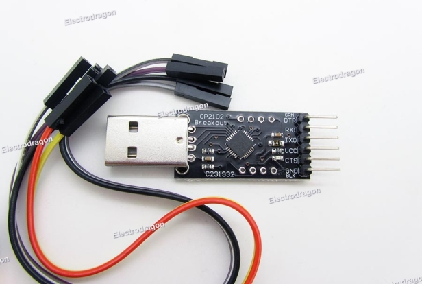
If your ESP32 board does not support USB port, you need to buy additional USB to UART module, like CP2102-USB-TTL-UART-Module-V2 as below , it will help you upload firmware to ESP32 and also helpful to use it to configure Ublox (or Navspark) module .
Testing.
After completing the component soldering, load the firmware for the ESP32 module.
Read this tutorial to Flash ESP32 : Flash/upload -Update Firmware for ESPrtk.
After pressing the reset button, 4 neopixel LEDs will change to 4 colors Green_Blue_White_Red, 2 blue status LEDs (Blue -Connect Status and Red-Error Status) will blink.
Some note.
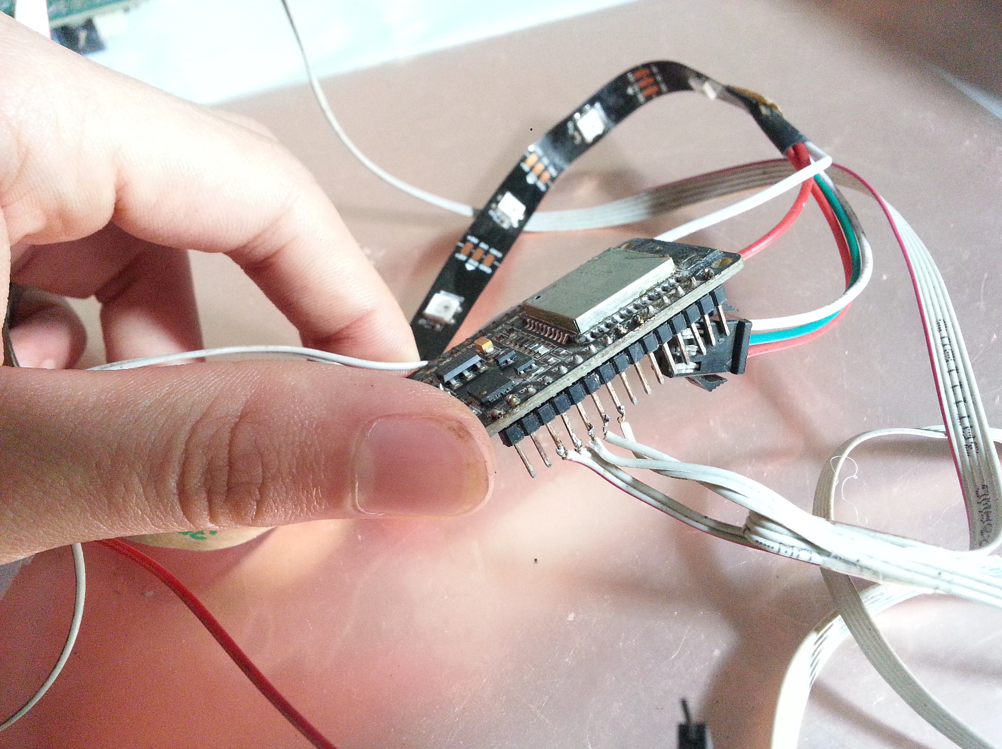
Proper polarity of the input data of the Neopixel strip.
![]()
![]()
Make sure the components work well before connecting them together.
Use a good power source.
It is not allowed to power the “5V_in” pin at the same time while connecting the circuit board to the USB cable that is connected to another power source. (You should only use 1 of 2 ways).
For complete applications, power should be supplied to the 5V pin instead of the power supplied via the USB cable, (because the USB cable is usually loose, the plated-steel contacts are rusted, resulting in poor electrical performance of voltage and Logic Level problem).
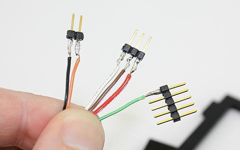
Make sure the connections are of the best quality to your current capabilities:
+ Use standard wire, not broken.
+Do not use jump wire or breadboard, you will fail because they will be extremely bad quality after a long time in used.

The best way to avoid these problems (and many unpredictable problems) is soldering electrical connections together !.

-
Version 1.0.0
-
Develop ESPrtk -
3. April 2019 um 12:58 -
25,1 MB -
53 Downloads
-