

Many thanks to all those from the Arduino chat who helped me with the Arduino basics. Here I present my solution, with which I can switch marking in Cerea both via an external switch, sensor or button, as well as via the lifting position of the EHR or the switching on and off of the PTO shaft.
I used an Arduino NANO. However, it should also be possible to use other Arduinos that have several digital inputs and at least one analog input, for which a wiring with 5 V is permissible.
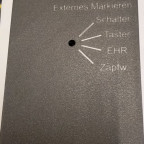
The criterion by which the sketch switches the marking, I choose with this 2 * 6 rotary switch:
Of the existing 6 switching stages, I use the following 5. The 6th is blocked with the enclosed lock.
1. Automatic marking disabled.
2. External switch. By connecting or disconnecting the signal line to the ground, marking is activated / deactivated. Since I have also inserted a +5V wire into the plug, an inductive PNP-NO-connected inductive proximity switch (e.g. this LJ12A3-4-Z / BX) can be connected instead of a switch without additional optocoplers, relays or other circuits. After I have mounted this on my seeder at the attachment of the arm of the spur wheel during excavation, the marking takes place in the sketch when the connection of the signal line to the ground is open or connected to 5V.
3. External push button. For the use of an external button instead of a switch, marking is activated or deactivated alternately when the contact is closed. There is no action when opening.
4. Signal socket - EHR excavation position. Marking is activated when the excavation switch is not in the lifting position. Unfortunately, it is not possible to distinguish between lowered or stop here with my tractor. Also, the actual height of the three-point linkage is not detected with my tractor via the corresponding pin of the signal socket.
5. Signal socket - PTO shaft. The analog measured value is buffered to an average value with the PTO shaft running via a series resistor and a capacitor., which the sketch interprets as an activity. On the other hand, if the ZW is at rest, this measured value either rises to high or falls to low, depending on the position of the pinion on the shaft. In both cases, marking imSketch is disabled. At the selected values for the resistance of 10 kOhm and 100 microfarads for the capacitor (electrolytic capacitor), the marking switches off from about 2 s rest of the PTO shaft. In order to achieve a faster reaction, a 10 microfarad Elko should be sufficient instead.
The two inputs fed by the signal socket are each reduced to a voltage below 5 V suitable for the Arduino NANO via a voltage divider with 6.8 / 4.7 kOhm and an additional Zener diode with a breakdown voltage of 4.7 V (1N4732).
The ZIP file of the download contains the sketch as well as a PDF file with the wiring diagram as I have executed it for me.
Wolfgang alias Wein-Franke
Subject to error - Reproduction at your own risk - Feel free to ask questions via PN or in the Arduino chat on Telegram
Edit 2023-02-27: The attempt to reduce the response time of the PTO function by a capacitor with a significantly lower capacitance leads to frequent interruptions. That's why I deleted the recommendation again.Translation by Yandex-Translate Bot on Telegram

-
Version 1.0.1
- Wein-Franke
- 3,38 kB
- 26 Downloads
Extension of the sketch:
the switching status can be detected via the LED of the Arduino Nano, which is connected in parallel to the digital PIN 13. To make sure that the sketch is loaded at all, I have integrated a flickering about every 3 seconds. (When marking is switched on, the LED gets off for a short time, or when marking is switched off, it lights up briefly.)
For wiring, the diagram in the ZIP-file of version 1.0.0 is still valid.
-
Version 1.0.0
- Wein-Franke
- 597,3 kB
- 90 Downloads